Page 127 - FLIPMAG.NET
P. 127

DIY WORKSHOP


                                                       2      3


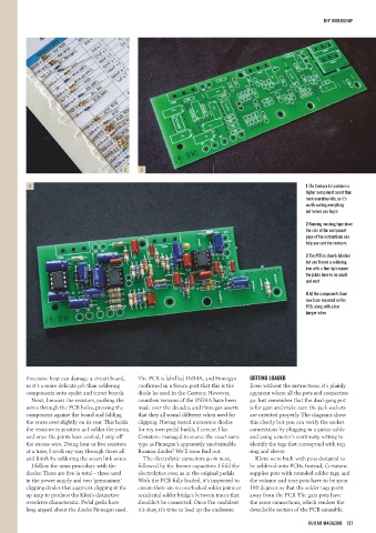
             4                                                                                                                       1 The Centura kit contains a
                                                                                                                                     higher component count than
                                                                                                                                     most overdrive kits, so it’s
                                                                                                                                     worth sorting everything
                                                                                                                                     out before you begin

                                                                                                                                     2 Running masking tape down
                                                                                                                                     the side of the component
                                                                                                                                     page of the instructions can
                                                                                                                                     help you sort the resistors


                                                                                                                                     3 The PCB is clearly labelled
                                                                                                                                     but you’ll need a soldering
                                                                                                                                     iron with a fine tip because
                                                                                                                                     the joints have to be small
                                                                                                                                     and neat

                                                                                                                                     4 All the components have
                                                                                                                                     now been mounted on the
                                                                                                                                     PCB, along with a few
                                                                                                                                     jumper wires


            Excessive heat can damage a circuit board,       The PCB is labelled 1N34A, and Finnegan         GETTING LOADED
            so it’s a more delicate job than soldering       confirmed in a forum post that this is the      Even without the instructions, it’s plainly
            components onto eyelet and turret boards.        diode he used in the Centaur. However,          apparent where all the pots and connectors
               Next, I mount the resistors, pushing the      countless versions of the 1N34A have been       go. Just remember that the dual-gang pot
            wires through the PCB holes, pressing the        made over the decades, and Finnegan asserts     is for gain and make sure the jack sockets
            component against the board and folding          that they all sound different when used for     are oriented properly. The diagrams show
            the wires over slightly on its rear. This holds   clipping. Having tested numerous diodes        this clearly but you can verify the socket
            the resistors in position as I solder the joints,   for my own pedal builds, I concur. Has       connections by plugging in a guitar cable
            and once the joints have cooled, I snip off      Ceriatone managed to source the exact same      and using a meter’s continuity setting to
            the excess wire. Doing four or five resistors    type as Finnegan’s apparently unobtainable      identify the tags that correspond with top,
            at a time, I work my way through them all        Russian diodes? We’ll soon find out.            ring and sleeve.
            and finish by soldering the seven link wires.      The electrolytic capacitors go in next,         Klons were built with pots designed to
               I follow the same procedure with the          followed by the brown capacitors. I fold the    be soldered onto PCBs. Instead, Ceriatone
            diodes. There are five in total – three used     electrolytics over, as in the original pedals.   supplies pots with rounded solder tags, and
            in the power supply and two ‘germanium’          With the PCB fully loaded, it’s inspected to    the volume and tone pots have to be spun
            clipping diodes that augment clipping in the     ensure there are no overlooked solder joints or   180 degrees so that the solder tags point
            op amp to produce the Klon’s distinctive         accidental solder bridges between traces that   away from the PCB. The gain pots have
            overdrive characteristic. Pedal geeks have       shouldn’t be connected. Once I’m confident      the same connections, which renders the
            long argued about the diodes Finnegan used.      it’s okay, it’s time to load up the enclosure.  detachable section of the PCB unusable.


                                                                                                                                       GUITAR MAGAZINE  127
   122   123   124   125   126   127   128   129   130   131   132